- Joined
- Dec 27, 2014
- Messages
- 6,181
- Reaction score
- 7,368
- Points
- 373
- Location
- Germany
- Printer Model
- L805, WF2010, ET8550, T3100X
Oh well, you asked for it .... I did it anyway to take it apart some more. Picture #2 above shows the nozzle plate , the bottom, and I took the metal frame around it away
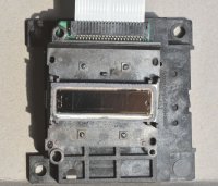
There is actually not much more to see, this nozzle plate has a width of 3 cm, we are here almost in the range of 1:1 macro takes.
The ink filters are now on the back of this assembly, the printhead sits on a smaller board on top of the wider one, and some electronics are covered behind it, with the flat cable connector.
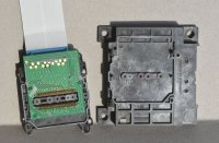
Now both are separated, the ink filters are on the back side of the right plate, and the ink flows through little gromets into the left assembly with the printhead, here on the backside.
Separating the little pc-board from the left mounting board shows this:
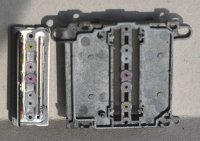
The little pc-board was mounted to the back of the right plastic part, the left is the printhead, with a connector bar broken away - the right board has two slits through which two multiconnector bars, metal, chip, flex pc-board are connecting the nozzles, making the electrical connections from the nozzles to the little pc-board removed above. The L300 uses 180 nozzles for black and 3x59 for the colors.
This image shows one of the connector bars somewhat mutilated, with connector wires connecting into the printhead and with a little flex pc-board with a chip on it, probably an address decoder to drive the nozzles, and there is the name of the company Sharp on this flex-board - on the right side - upside down - which let me assume that the actual printhead assembly is subcontracted to Sharp by Epson, or Sharp is selling them their printheads.
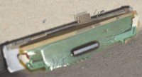
The ink flows into through various gromets into the nozzle assembly which I did not brake apart, that looks pretty much and firmly glued together. This little left over broken part is less than 3 cm wide. It fits vertically into the gap in the nozzle plate in picture #7, and you can see the corresponding contacts at the bottom of that slit.
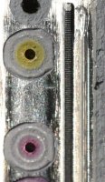

There is actually not much more to see, this nozzle plate has a width of 3 cm, we are here almost in the range of 1:1 macro takes.
The ink filters are now on the back of this assembly, the printhead sits on a smaller board on top of the wider one, and some electronics are covered behind it, with the flat cable connector.

Now both are separated, the ink filters are on the back side of the right plate, and the ink flows through little gromets into the left assembly with the printhead, here on the backside.
Separating the little pc-board from the left mounting board shows this:

The little pc-board was mounted to the back of the right plastic part, the left is the printhead, with a connector bar broken away - the right board has two slits through which two multiconnector bars, metal, chip, flex pc-board are connecting the nozzles, making the electrical connections from the nozzles to the little pc-board removed above. The L300 uses 180 nozzles for black and 3x59 for the colors.
This image shows one of the connector bars somewhat mutilated, with connector wires connecting into the printhead and with a little flex pc-board with a chip on it, probably an address decoder to drive the nozzles, and there is the name of the company Sharp on this flex-board - on the right side - upside down - which let me assume that the actual printhead assembly is subcontracted to Sharp by Epson, or Sharp is selling them their printheads.

The ink flows into through various gromets into the nozzle assembly which I did not brake apart, that looks pretty much and firmly glued together. This little left over broken part is less than 3 cm wide. It fits vertically into the gap in the nozzle plate in picture #7, and you can see the corresponding contacts at the bottom of that slit.

Last edited:

