Dr_Nick
Newbie to Printing
- Joined
- Feb 26, 2025
- Messages
- 6
- Reaction score
- 2
- Points
- 8
- Printer Model
- Canon TS8350
Hi, first time posting here.
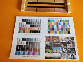
I have 3D-printed the two-part scanning jig and I have used it with the 480 patch argyll target provided by @pharmacist . I scanned the target with my ColorMunki Design device and obtained very low dE values (max of 1.3 or something like that). I followed the procedure describe here. However, the white point of the profile (as shown on iccview.de for instance) is signficantly lower than for a profile obtained with ccStudio on the same paper (Canon SG-201 paper, see below).
Both profiles provide good-looking prints when tested on popular printer test images (for instance the "Outback print image") but I still worry about the white point.

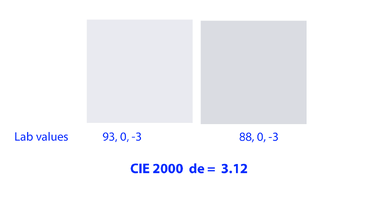
Using the spotread command I noticed that argyll measures a LAB value of about -93 / 0 / -3 when the instrument is pressed on the paper (much closer to the value found by the xrite Software), but that value drops to about -88 / 0 / -3 when it is put on the scanning jig - consistent with my profile.
I believe the ColorMunki must be pressed against the paper but when it sits on the scanning jig there's an almost 2 mm gap between the hole of the instrument and the paper. That likely causes some light diffusion, thus the lower L value? Actually when I press the instrument on the paper and tilt it only very slightly (like 1mm) this is enough to have a lower L reading...
Can you confirm this on your side?
I should mention that my jig is made of white PETG but painting the inside of the slit in black did not change anything.
I have 3D-printed the two-part scanning jig and I have used it with the 480 patch argyll target provided by @pharmacist . I scanned the target with my ColorMunki Design device and obtained very low dE values (max of 1.3 or something like that). I followed the procedure describe here. However, the white point of the profile (as shown on iccview.de for instance) is signficantly lower than for a profile obtained with ccStudio on the same paper (Canon SG-201 paper, see below).
Both profiles provide good-looking prints when tested on popular printer test images (for instance the "Outback print image") but I still worry about the white point.
Using the spotread command I noticed that argyll measures a LAB value of about -93 / 0 / -3 when the instrument is pressed on the paper (much closer to the value found by the xrite Software), but that value drops to about -88 / 0 / -3 when it is put on the scanning jig - consistent with my profile.
I believe the ColorMunki must be pressed against the paper but when it sits on the scanning jig there's an almost 2 mm gap between the hole of the instrument and the paper. That likely causes some light diffusion, thus the lower L value? Actually when I press the instrument on the paper and tilt it only very slightly (like 1mm) this is enough to have a lower L reading...
Can you confirm this on your side?
I should mention that my jig is made of white PETG but painting the inside of the slit in black did not change anything.
Last edited: