Using ArgyllCMS + Colormunki to produce excellent printer profiles

supergrobi

Printing Apprentice
Joined
Mar 5, 2015
Messages
8
Reaction score
8
Points
17
Location
Germany, Bavaria :)
Printer Model
HP Z3200 24" / 2x HP B9180 A3+
Perhaps, read it with a black mask and without the mask and compare them with the "colverify" command?
 

RogerB

Print Addict
Joined
Sep 27, 2010
Messages
293
Reaction score
316
Points
183
Location
S.E. England
Printer Model
Epson Pro3880
My afterthought is that this black mask may not be completely "black" and may reflect some light and disturb the reading. I'm trying to get the strips at least 7mm wide.
The light source of the i1Pro produces a conical annulus so that the measurement area is illuminated at 45 degrees from all orientations. Imagine a cone with an included angle of 90 degrees with its apex in the measurement plane. If you lift the measuring head the light is no longer focussed on the target and the L* reading gets lower - in other words the target looks darker. If you hold the measuring head about 5mm above a white surface it will tell you that the surface is completely black!

As I said - be very careful.
 

nrdlnd

Fan of Printing
Joined
Jan 19, 2015
Messages
74
Reaction score
31
Points
63
Printer Model
Epson Stylus Pro 3880
As I said - be very careful.

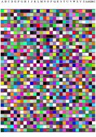
An idea could be to paint or glue some black fabric in the slot to reduce reflections. The opening it's too wide anyway. I've now managed to make an A4 chart for the i1 Pro with 968 patches 22 in the row and 44 rows. The patches are 6.9 mm wide. Printtarg a0.84 and a custom paper size 370x235mm to start with (the slot in the ruler for the i1 Pro isn't long enough to read long A4 strips lengthwise so it has to be horizontal). Then I did cut off the text on the right side of the chart and moved the row letters nearer the patches. I then cropped the chart. The cropped size of the chart is almost A4 and the same proportions but I did a small resize to get A4 (297x210 mm in my case). I printed it with the simple Adobe Color Printing Utility (available without cost). Horizontal format with zero (0) margins. In the printer driver appropriate paper and quality settings and of course no color adjustment. I then went into the page layout setting in the driver and there I ticked reduce/enlarge and ticked custom and set it to 102%. I had to experiment as 105% didn't print the whole chart. This printed almost perfectly with 3 mm white margins all around and 6.9 mm wide patches. Borderless didn't work as the whole chart wasn't printed.

I suggest you also try at least 30% grey scale patches to improve the overall quality of the profile.

In this chart I have white patches = 8, black patches = 4, composite grey steps = 128. Emulator should I set g320 (instead of g128) in Targen to get 30% grey scale patches or what number should it be?

I will later repeat the process for Letter Size as I have some Museo Papers 17"x22" that I cut to Letter Format for profiling. I do also cut 17" rolls. The tricky thing is to get the cropped page to have the same proportions as the paper to print on and to get a good patch size.

Per
 

Attachments

  • standard_profile_968_a0.84.jpg
    standard_profile_968_a0.84.jpg
    76.4 KB · Views: 503

supergrobi

Printing Apprentice
Joined
Mar 5, 2015
Messages
8
Reaction score
8
Points
17
Location
Germany, Bavaria :)
Printer Model
HP Z3200 24" / 2x HP B9180 A3+
Emulator should I set g320 (instead of g128) in Targen to get 30% grey scale patches or what number should it be?

Good question. I will try to double the 128 steps and print 256 gray scale patches and 8 white + 8 black patches. I think 256 steps will be enough? 8 white patches to get the paper color more accurate, and also 8 black patches.

targen -v -d2 -G -e8 -B8 -g256 -f954 profile_name

printtarg -v-ii1 -a0.7 -T360 -m2 -P -pA4 profile_name

This will produce 986 patches, cropped and stretched to A4 with a width of 7mm. 29 columns and 34 rows.
256 gray scale, 8 black / 8 white patches.

test2.jpg
hopefully i can manage the reading of the patches, i will read it twice an compare the results.
 

Emulator

Printer Master
Platinum Printer Member
Joined
Jan 4, 2012
Messages
1,675
Reaction score
1,308
Points
277
Location
UK
Printer Model
Canon Pro9000 II
Have you looked through
A basic guide (see post #1) to setting up ARGYLL CMS profiling on your computer

It is rather a long thread, but many of these matters have already been discussed, I work with the ColorMunki photo and some of these ideas, while working with the CM are not appropriate with the I1.

You will see in post#1 of the above thread that there is a CAP957.txt file and a 33% greys file, which you can view or download and use to create profiles, it gives you all the Argyll lines, built into a batch file ready to run or copy.
 

RogerB

Print Addict
Joined
Sep 27, 2010
Messages
293
Reaction score
316
Points
183
Location
S.E. England
Printer Model
Epson Pro3880
In this chart I have white patches = 8, black patches = 4, composite grey steps = 128. Emulator should I set g320 (instead of g128) in Targen to get 30% grey scale patches or what number should it be?
Per
FWIW I find with my 3880 that I get very good greyscale performance with just 64 grey patches. The "K3" printers have a nice smooth greyscale native response which doesn't need too much correction so I'm not sure I would sacrifice so many colour patches. Interestingly the Xrite 918-patch target has only 27 grey patches, but still produces very good greyscale for most K3 printers.
 

nrdlnd

Fan of Printing
Joined
Jan 19, 2015
Messages
74
Reaction score
31
Points
63
Printer Model
Epson Stylus Pro 3880
The light source of the i1Pro produces a conical annulus so that the measurement area is illuminated at 45 degrees from all orientations. Imagine a cone with an included angle of 90 degrees with its apex in the measurement plane. If you lift the measuring head the light is no longer focussed on the target and the L* reading gets lower - in other words the target looks darker. If you hold the measuring head about 5mm above a white surface it will tell you that the surface is completely black!

The clearance from the head of i1 Pro in the ruler to the chart is about 0.5mm. The measurement opening is 4.3-4.4mm. If the illumination is 45 degrees then I calculate that the paper is illuminated with a diameter about 5.4mm (in the spec they say 4.5mm and 6mm respectively but I measure it a little smaller). There may be reflections from nearby strips via the underside uf the ruler but they may be at such an angle that they don't interfere with the reading. What is possible to do is to place some small round piece of black material less than 0.5mm thick around the measurement opening to cancel reflections. It's possible to stamp such a piece. In this way the distance between the meter and the chart isn't changed.
 

supergrobi

Printing Apprentice
Joined
Mar 5, 2015
Messages
8
Reaction score
8
Points
17
Location
Germany, Bavaria :)
Printer Model
HP Z3200 24" / 2x HP B9180 A3+
I used the CAP957.txt (batch) file to create a profile and recorded a photoshop action for cropping and resizing the *.tif image, it works perfectly.
My first test print looks fine, i used relative colormetric intent with BPC, the brightness is very close, great colors :)
@Emulator: many thanks for the great link and your work to put all the informations together. :bow

The width of the patches is 7mm. I used the colormunki software to scan some single patches to get the color information, i placed the colormunki with it´s litte target device by hand without covering the nearby patches and got some pretty good values, i don´t think it´s so prone to error. I thinks it measures the direct reflection of the spot from above without scattering from the neary patches.
 

RogerB

Print Addict
Joined
Sep 27, 2010
Messages
293
Reaction score
316
Points
183
Location
S.E. England
Printer Model
Epson Pro3880
There may be reflections from nearby strips via the underside uf the ruler but they may be at such an angle that they don't interfere with the reading. What is possible to do is to place some small round piece of black material less than 0.5mm thick around the measurement opening to cancel reflections. It's possible to stamp such a piece. In this way the distance between the meter and the chart isn't changed.
The illumination is at 45 degrees but the measurement is at 0 degrees, so it is unlikely that stray reflections will be significant. I suspect that the diameter of the measurement spot is defined by the optics of the sensor rather than by the illumination.
 

nrdlnd

Fan of Printing
Joined
Jan 19, 2015
Messages
74
Reaction score
31
Points
63
Printer Model
Epson Stylus Pro 3880
The illumination is at 45 degrees but the measurement is at 0 degrees, so it is unlikely that stray reflections will be significant. I suspect that the diameter of the measurement spot is defined by the optics of the sensor rather than by the illumination.

OK I think I can buy that! It's actually my own thought that the reflections may be insignificant. The proof is to make the experiment but I may be to lazy to do it. Anyway I think it's a good practice not to make the strips/patches too narrow. It's important to position the meter carefully to avoid reading nearby patches.

The Colormunki is quite another device. The opening from the meter is 7mm and the optics are placed more far from the opening. Probably it will illuminate a wider area but depending on the optics it could read a much smaller area than that and maybe also less sensitive to the distance to the chart as in other posts it has been said that the distance is not so important. Theoretically it should be important that if the focal length is longer then there are smaller margins! I haven't seen any specifikations of the Colormunki.
 
Top