Colormunki/ArgyllCMS profile lacking dark tones (compared to ccStudio)

lmylm

Printing Apprentice
Joined
Feb 17, 2024
Messages
14
Reaction score
9
Points
10
Printer Model
Inkjet
Hi! A few months ago I started getting into home photo printing. I found my photo prints to have colors that did not really match the ones on my calibrated screen. Mostly I realized a magenta tint, especially on people’s faces.

After reading a lot on websites and in Internet forums like this one, I got myself a used Colormunki Photo and started profiling my papers. First I used ccStudio by X-Rite, just to start out with the Software this Hardware is intended for. After this seemingly worked I wanted to use ArgyllCMS as I read that the profile precision/accuracy is supposed to be much better when profiling with this software.

I was heavily disappointed when I used the resulting ArgyllCMS profile. The soft proof was dull already, no comparison to the profile I created with ccStudio. The darker tones are completely lost.

Here is an example in the form of soft proof crops of water ripples (when printing using each profile I get a result that very closely resembles the respective soft proof):

water_original.png

Original
water_ccstudio.png

ccStudio
water_argyllcms.png

ArgyllCMS

The paper I profiled here is matte and my printer uses dye inks. So the low black levels I got from ccStudio is what I expected. What I did not expect are the non-existing black levels in the ArgyllCMS profile.

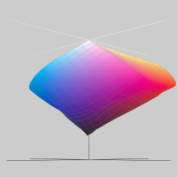
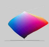
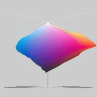
To further investigate I then compared the resulting profiles in ColorSync Utility:

ccStudio

ccStudio
ArgyllCMS

ArgyllCMS

With my superficial knowlegde the reason for the missing darker tones with the ArgyllCMS profile seems to be obvious. The ArgyllCMS doesn’t “have” them. Do I need to tell ArgyllCMS to somehow stretch the profile like ccStudio apparently did?

For the ArgyllCMS profile creation I used parmacists great post and the article by Anders Torger as base information for my profiling with ArgyllCMS.

I ended up with these commands:

Bash:
targen -v -d2 -G -g8 -f210 $PROFILENAME
printtarg -v -iCM -h -R1 -T300 -p A4 $PROFILENAME
chartread -v -H -T0.4 $PROFILENAME
colprof -v -qh -S AdobeRGB1998.icc -cmt -dpp $PROFILENAME

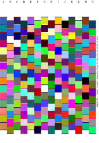
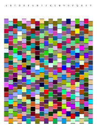
Producing this target sheet:

profile1.png

I really hope someone is able to shed some light on this.

UPDATE: Here is a scan of three actual prints (ArgyllCMS, Original, ccStudio):
compared-jpg.15969

For details see https://www.printerknowledge.com/th...-tones-compared-to-ccstudio.16373/post-141537
 
Last edited:

Ink stained Fingers

Printer VIP
Platinum Printer Member
Joined
Dec 27, 2014
Messages
6,061
Reaction score
7,234
Points
363
Location
Germany
Printer Model
L805, WF2010, ET8550
The soft proof was dull already,
Please post the target sheet with all the color patches - save and load the file in .png format if you can - not as .tiff - .png is much smaller.

(I'm not an ArgyllCMS user and cannot create the file by myself)

It all starts with the color patches - the patch sheet may miss the darker tones altogether.
 

Ink stained Fingers

Printer VIP
Platinum Printer Member
Joined
Dec 27, 2014
Messages
6,061
Reaction score
7,234
Points
363
Location
Germany
Printer Model
L805, WF2010, ET8550
Imylm - you refer to a ArgyllCMS profiing guide by Andreas Torger

https://torger.se/anders/photography/argyll-print.html

which is a very comprehensive article, he made a test about the accuracy of profiles vs. the color patch count; I did a kind of similar test recently with the i1profiler software and come to some similar conclusion that profiles based on a small patch count are already pretty accurate compared to a profile with a much higher count - I did it against 2880 patches.

https://www.printerknowledge.com/threads/profiling-target-sheet-patch-count.16326/
 

lmylm

Printing Apprentice
Joined
Feb 17, 2024
Messages
14
Reaction score
9
Points
10
Printer Model
Inkjet
Please post the target sheet with all the color patches - save and load the file in .png format if you can - not as .tiff - .png is much smaller.

(I'm not an ArgyllCMS user and cannot create the file by myself)

It all starts with the color patches - the patch sheet may miss the darker tones altogether.
Thank you so much for your reply. I added the used target sheet as PDF to my original post. It would surprise me if ArgyllCMS would leave out essential patches. Especially using the parameters from the mentioned tutorials.

Imylm - you refer to a ArgyllCMS profiing guide by Andreas Torger

https://torger.se/anders/photography/argyll-print.html

which is a very comprehensive article, he made a test about the accuracy of profiles vs. the color patch count; I did a kind of similar test recently with the i1profiler software and come to some similar conclusion that profiles based on a small patch count are already pretty accurate compared to a profile with a much higher count - I did it against 2880 patches.

https://www.printerknowledge.com/threads/profiling-target-sheet-patch-count.16326/
Yes, Andreas Torger’s article seems to leave nothing open. They seem like a very knowledgeable person. This article as well as the post you linked and all other sources I found suggest that profiling with Colormunki using ArgyllCMS is much more accurate that using ccStudio. That’s why I wonder: where is the mistake in my workflow?
 

Ink stained Fingers

Printer VIP
Platinum Printer Member
Joined
Dec 27, 2014
Messages
6,061
Reaction score
7,234
Points
363
Location
Germany
Printer Model
L805, WF2010, ET8550
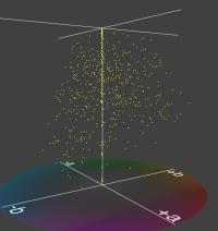
I'm trying to understand how the colors of your patch sheet are distributed across the Lab color space - where your 400 to 600... colors are located. The first problem with your patch sheet - not actually yours but generated apparently by ArgyllCMS is the patch sheet setup - you have the colors of the patches - and lots of additional colors of the separating lines between the patches - just do a lookup of total colors of such patch file - there is typically a function in image editors like 'count unique colors' , you get plenty more - something like 2850 colors which very much disturb the display of the patch colors . The Monaco Gamutworks old software can display a graphics file as a pixel cloud in the Lab space. The display is in 3D which I cannot replicate here in my posting which makes it more difficult to understand the display in 2D.


Profile1.PNG

The pixels are not distributed very equally in the 3D color space - there are barely any in the darker range - L below 20 (along the vertical axis L) at the bottom.

I don't know at this time what this means - which impact it has on the data calculations to generate the
data for the various A to B and B to A files/LUT - lookup tables - in the icm profile.

Please be aware that this finding is just an obseration at this time.
 

pharmacist

Printer VIP
Platinum Printer Member
Joined
May 29, 2007
Messages
2,646
Reaction score
1,411
Points
313
Location
Ghent, Belgium
Printer Model
2x SC-900, WF-7840, TS705
Try this set of mine: you will need a custom made ruler to guide the Colormunki over these tiny patches. Anyhow: 210 patches are too low to get a satisfactory profile. You will need at least 400-500 to get a satisfactory profile with ArgyllCMS with a predictable (linear behaving) printer.
 

Attachments

  • 480target-A4-ArgyllCMS-with-entry-form.zip
    892.9 KB · Views: 121

lmylm

Printing Apprentice
Joined
Feb 17, 2024
Messages
14
Reaction score
9
Points
10
Printer Model
Inkjet
I'm trying to understand how the colors of your patch sheet are distributed across the Lab color space - where your 400 to 600... colors are located. The first problem with your patch sheet - not actually yours but generated apparently by ArgyllCMS is the patch sheet setup - you have the colors of the patches - and lots of additional colors of the separating lines between the patches - just do a lookup of total colors of such patch file - there is typically a function in image editors like 'count unique colors' , you get plenty more - something like 2850 colors which very much disturb the display of the patch colors . The Monaco Gamutworks old software can display a graphics file as a pixel cloud in the Lab space. The display is in 3D which I cannot replicate here in my posting which makes it more difficult to understand the display in 2D.


View attachment 15922

The pixels are not distributed very equally in the 3D color space - there are barely any in the darker range - L below 20 (along the vertical axis L) at the bottom.

I don't know at this time what this means - which impact it has on the data calculations to generate the
data for the various A to B and B to A files/LUT - lookup tables - in the icm profile.

Please be aware that this finding is just an obseration at this time.
Thank you for the detailed insight. To clarify: the coloured borders separating the patches in the target sheet are generated by default. Anders Torger’s tutorial also creates these borders. It would surprise me if Anders’ Colormunki would not have problems with the separator but mine does.

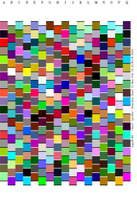
Anyways, yesterday I made another profile using an ArgyllCMS target specifying -b for forcing black/white borders. Here you can see the target sheet and the barely changed resulting profile:

target2.pngprofile2.png

So, the coloured borders didn’t matter. The problem lies somewhere else. Thanks for your effort anyways. I really appreciate it!

Try this set of mine: you will need a custom made ruler to guide the Colormunki over these tiny patches. Anyhow: 210 patches are too low to get a satisfactory profile. You will need at least 400-500 to get a satisfactory profile with ArgyllCMS with a predictable (linear behaving) printer.
Thank you very much. I might try out your exact pattern, even though I hardly believe that this will change anything.

According to Anders Torger’s article 210 patches are enough to create a more accurate profile than with ccStudio: “a single A4 sheet, still more accurate than Colormunki's bundled software”. Everything I want at this point is a profile equally good or better as the one created by ccStudio (see in my original post). ccStudio uses 100 patches only, yet it delivers a better profile than my 210-patch ArgyllCMS profile. So I don’t really see how my ArgyllCMS patch count can be a problem here.

I also tried 323 and 420 patches, getting the same result. Here is the visualisation of another ArgyllCMS profile for another paper (satin, with a higher gamut). As you can see the black level here also doesn’t reach the bottom, even though I used 420 patches (which is within the 400-500 patches you suggest to use).

target420.png420.png

I tried out many many different patch counts. The black point in the resulting profiles was always the same. The number of patches did not have any effect on this. Keep in mind that the above example (where the black point is a bit lower) was done on different paper. It is not the patch count that made the change here.

My assumption is that there is nothing wrong with the target sheet or the reading of it. To me it seems like the generation of the ICC profile should be stretching the black point of the profile down to absolute black. Yet neither your parameters nor Anders’ seem to be doing that:

Bash:
colprof -v -qh -i D50 -o 1931_2 -S AdobeRGB1998.icc -cmt -dpp -D"X" -CY standard_profile # pharmacist
colprof -v -qh -r1.0 -S AdobeRGB.icc -cmt -dpp -D"<description>" <name> # Anders Torger

I might be completely wrong about that as I am a total newbie to color profiles. All I see is the two profiles (ccStudio vs. ArgyllCMS) and the my prints using the ccStudio profile look good and the ones using the ArgyllCMS profile don’t. The obvious difference between the profiles is that one reaches the black bottom while the other one doesn’t.
 

Ink stained Fingers

Printer VIP
Platinum Printer Member
Joined
Dec 27, 2014
Messages
6,061
Reaction score
7,234
Points
363
Location
Germany
Printer Model
L805, WF2010, ET8550
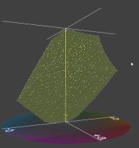
Let me display @pharmacist 's 480 patch file in the Lab color space - the colors of the spots are pretty regularly distributed across the Lab display volume - yellow spots - I'm overlaying it with the gamut volume of the sRGB color space - shaded in green. Color spots of the target sheet are located at all corners and along all edges and inside the volume in about equal distance, that's quite a similar view of target sheets generated by XRite software - i1Profiler in my case.
(Sorry - I cannot give you the 3D functionality here with the Monaco software)


480.PNG
 

lmylm

Printing Apprentice
Joined
Feb 17, 2024
Messages
14
Reaction score
9
Points
10
Printer Model
Inkjet
Last edited:

lmylm

Printing Apprentice
Joined
Feb 17, 2024
Messages
14
Reaction score
9
Points
10
Printer Model
Inkjet
@Ink stained Fingers @pharmacist

OT: You guys seem to be able to see and answer to my posts even though they are held back for moderator approval. Does that mean you are moderators and keep forgetting to approve my messages? :)
 
Top